

Simple delay circuit pspice model full#
Tutorial number four: Half wave and full wave rectifier. Developing Subcircuit Models using PSpice Model Editor Cadence Design Systems 28K subscribers Subscribe 13 2.4K views 1 year ago Knowledge and Learning Use PSpice Model Editor to develop. Tutorial number three: RL, RC and RLC circuits simulations in pspice. Tutorial number two : Getting started with simulation software.
Simple delay circuit pspice model how to#
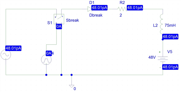
How to design RL and RC circuit in PSPICE popular SPICE circuit simulator is extended to analyze digital circuits at the. Tutorial number one: Download and installation you will learn how to download and install it with step by step guide. This leading and lagging of current and voltage in case of RC and RL circuits will be explained in this tutorial. Step 3: Select Capture as your Design Entry Tool and click Done. Step 2: Open PSpice Model Editor 17.4 (Start > Cadence PCB Utilities 17.4-2019 > PSpice Model Editor 17.4). Note: To follow along with this blog, download the provide spice model: 2N6661SPICE.lib. Similarly, if we introduce an inductor in a simple resistive circuit, the output current will be leading the output voltage by 90 degrees. Step 1: Download the desired SPICE Model. The introduction of a capacitor in a simple resistive circuits results in the voltage lead of 90 degrees from the current. Another simple way to kick-start an oscillator based on a tuned circuit is to replace a simple DC supply source with a PULSE source set to an initial level of. The very basic circuits in electrical engineering are RC and RL circuits, these circuits are analyzed only to test the behavior of capacitor and inductor on current and voltage. At the end of the tutorial you are provided with an exercise to do it by yourself, and in the next tutorials I will assume that you have done those exercises and I will not explain the concept regarding them. The use of a diode and a capacitor toeliminate circuit response delays (Fig. Capture/OrCAD Capture CIS library of parts for general schematic entry. After that the concept provided in introduction part is implemented with the help of PSPICE, and the theoretical results are compared with the virtual results of PSPICE which comes out to be same. 1.2)with a square wave input is explored. First the brief and concise introduction of capacitive and inductive circuits is provided explaining the effect of introducing each of them in a resistive circuit. In this tutorial, I will explain you the working of RC and RL circuit.


 0 kommentar(er)
